Compose a 3-tier Application (UI)
Objectives
In this tutorial we will show you how to use the AMP UI to deploy a three-tier web application.
Pre-requisites
This tutorial assumes you have installed Cloudsoft AMP.
It also requires a deployment location configured to use Ubuntu 22.04 or similar.
To create one in AWS, you can use the Location Manager from the nine-dots menu selector
in the top right of the UI, as described in the installation.
Click “Add new” then “Cloud”, choose an ID such as aws-ubuntu, AWS EC2,
region eu-west-2,
enter your identity (access key) and credential (secret key),
and add the following “additional configuration” keys (before the => below),
press enter, then enter the given value (after the =>), and then click “Save”:
imageId=>eu-west-2/ami-07c2ae35d31367b3eloginUser=>ubuntu
Finally, it is assumed that you have downloaded threetier.zip and imported it
into AMP: open the Catalog and click Upload to Catalog, then drag and drop that ZIP bundle.
This provides the individual components we will use to build thre three-tier app in the AMP UI.
The next tutorial will show how the individual components are built.
Instructions
Select the Blueprint Composer from the Home page or the module menu on the top right of the screen. This module is composed of 3 main parts:
- The
canvas: this is where is displayed the graphical representation of the blueprint you are creating. - The
palette: that is the box on the left to choose and add entities/policies/enrichers. - The
spec editor: that is the box on the right to view and edit the currently selected node.
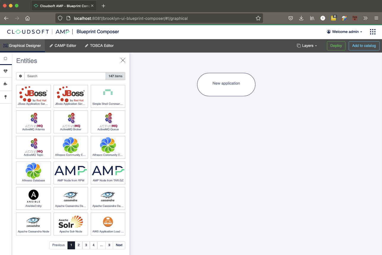
The top node represents the application node. This is usually where you will set the location for the entire blueprint, unless you wish to deploy parts on different clouds.
Adding the database tier (MySQL)
Add a node for the database by searching the palette for the type named io.cloudsoft.smart-mysql-node . You can then drag & drop it onto the application node.
Alternatively, you can click on the entity in the palette and click the button Add to application.
Once the entity is added into the graph, a new node will appear and the spec editor will then be displayed.
Set a name by entering My DB (MySQL) instead of io.cloudsoft.smart-mysql-node. Do the same for the ID by entering db instead of the generated ID.
Finally, edit the mysql_creation_script configuration key and set it to the following value:
classpath://io.cloudsoft.brooklyn.tosca13.tosca-3-tier:resources/creation-script-mysql.sql
Your screen should now look like something similar to this:
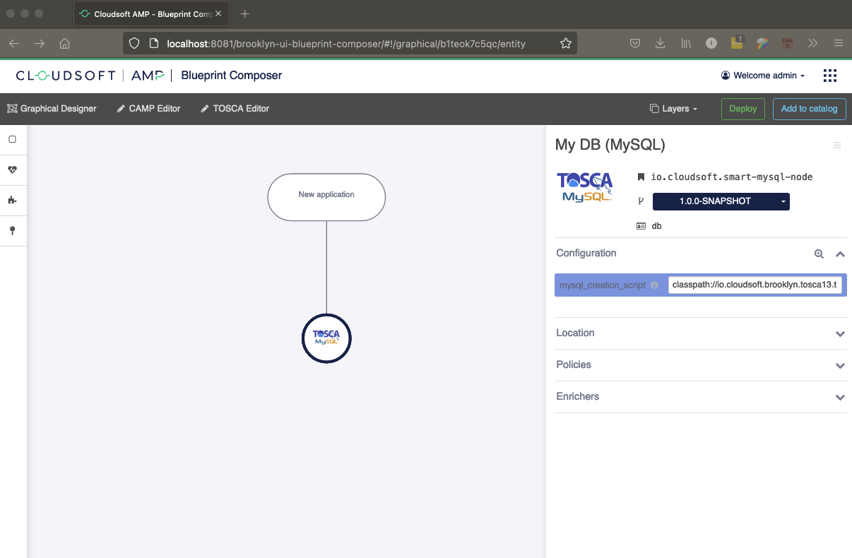
Note: io.cloudsoft.smart-mysql-node attempts to download MySQL from the public internet and install it if it is not pre-installed on the VM. Also, this type is suitable for deployment on an Ubuntu 20 VM.
Adding the Web Tier (Cluster of Tomcat)
Add a node for the web cluster by searching the palette for the entity named DynamicCluster or the full type name, i.e. tosca.entity.DynamicCluster and drag & drop it onto the application node.
Once the entity is added into the graph, a new node will appear and the spec editor will then be displayed.
Set a name by entering My Cluster instead of Dynamic Cluster. Do the same for the ID by entering cluster instead of the default value.
On the Configuration accordion, set the suggested Initial size (cluster.initial.size) configuration key to: 2.
all.
Set the Member spec (dynamiccluster.memberspec) configuration key by clicking on No spec set. The palette will once again be displayed.
Select io.cloudsoft.smart-tomcat9-node and enter the following configuration keys (Configuration accordion):
tomcat_deploymentwith valueclasspath://io.cloudsoft.brooklyn.tosca13.tosca-3-tier:resources/tosca-hello-world-sql-webapp.wartomcat_db_urlwith value$brooklyn:component("db").attributeWhenReady("db_instance_url")tomcat_db_driverwith value$brooklyn:component("db").attributeWhenReady("db_instance_driver")
Optionally you can rename the spec node from io.cloudsoft.smart-tomcat9-node to Apache Tomcat Member. It is recommended to do so, for more visibility in the App Inspector.
Note: io.cloudsoft.smart-tomcat9-node attempts to download Tomcat 9 from the public internet and install it if it is not pre-installed on the VM. Also, this type is suitable for deployment on an Ubuntu 20 VM.
The spec editor should now display something similar to this: 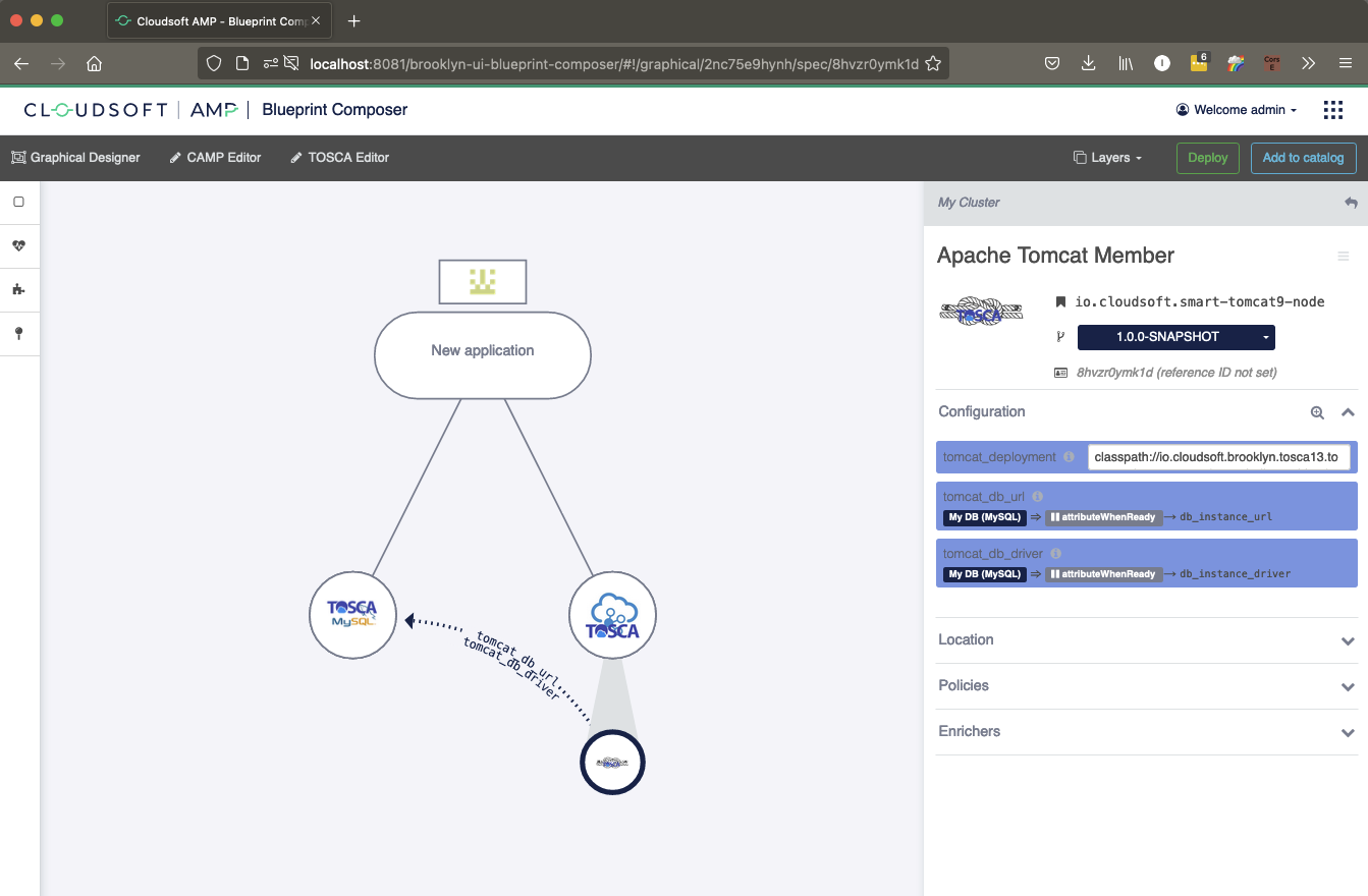
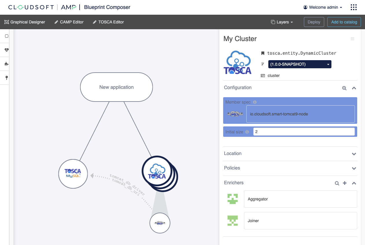
Go back to the web cluster entity by clicking on the My Cluster cluster node on the graph. Head over the Enrichers
accordion and click on the “+” icon. Similar to the cluster member spec in the previous step, search and select
the Aggregator enricher and clearing any filters if necessary, add the following configuration keys
(Configuration accordion):
enricher.sourceSensorwith value$brooklyn:sensor("app.endpoint")enricher.targetSensorwith value$brooklyn:sensor("addr.list")enricher.aggregating.fromMemberswith valuetrue
Head over the Enrichers accordion again and click on the “+” icon and add Joiner with the following configuration
keys (Configuration accordion):
enricher.joiner.minimumwith value$brooklyn:config("cluster.initial.size")enricher.sourceSensorwith value$brooklyn:sensor("addr.list")enricher.targetSensorwith value$brooklyn:sensor("addr.list.string")enricher.joiner.separatorwith value,
The canvas and the spec viewer should now display something similar to this:
Add a node for the web cluster by searching the palette for the entity named Load Balancer (nginx) or the full type name, i.e. tosca-nginx-node and drag & drop it onto the application node. Set a name by entering My Load Balancer (nginx) instead of Load Balancer (nginx) for the tosca-nginx-node. Modify the ID by entering nginx-instance instead of tosca-nginx-node.
For the nginx-instance node, on the Configuration accordion, search for:
nginx.stickyconfiguration key and set the switch tofalseaddr.listconfiguration key and enter the following value:$brooklyn:entity("cluster").attributeWhenReady("addr.list.string")
Note: tosca-nginx-node attempts to download NgiX from the public internet and install it if it is not pre-installed on the VM. Also, this type is suitable for deployment on an Ubuntu 20 VM.
Add a tosca.nodes.Compute to the application and set its id to nginx-host. Make this node a host for nginx-instance. Click on thenginx-instance node and in the spec editor expands the Requirements tab and set the host to nginx-host.
To do this, click on the nginx-host node and in the spec editor, edit the capabilities property. Set it to the following value:
{
  "cloudsoft": {
    "properties": {
      "required.ports": "$brooklyn:component(\"nginx-instance\").config(\"app.port\")"
    }
  }
}
The canvas and the spec viewer should now display something similar to this: 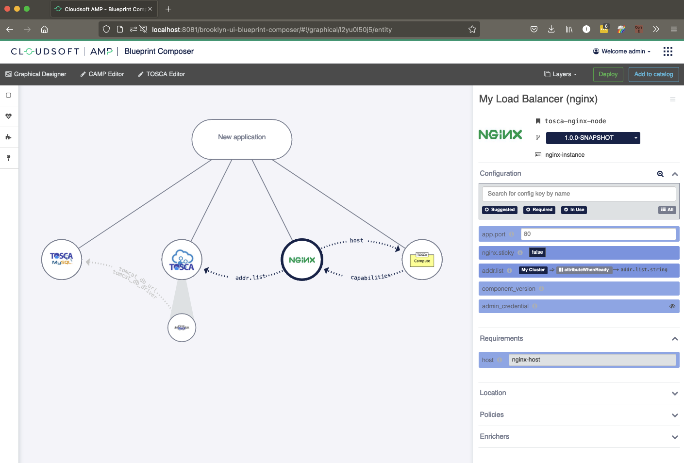
Setting the Application Title, Location and Propagate Valuable Sensor
Click on the application node (where it currently says New application) to bring up the spec editor.
Set a name by entering My Web Cluster instead of Unnamed Application.
TOSCA is ordinarily configured with a default location.
If this is not done, or you wish to use a different location for this application,
open the Location accordion and click on the Attach link.
This will display the palette with all available locations you can deploy your blueprint to.
Select the one you wish to use.
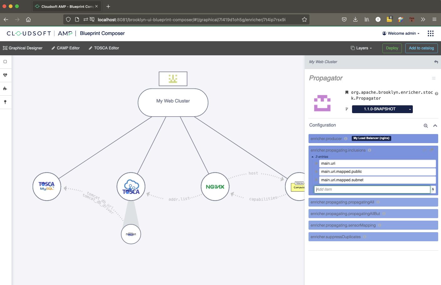
Finally, head over the Enrichers and click on the “+” icon. Similar to the cluster member spec in the previous step, search and select the Propagator enricher and add the following configuration keys (Configuration accordion):
enricher.producerwith value (or use the DSL editor to target thenginx-instanceentity)$brooklyn:entity("nginx-instance")enricher.propagating.inclusionswith valuemain.uri
The canvas and the spec viewer should display something similar to this:
Note: Although this is a deployable application, for a real life three tier application designed using this model, additional aggregators, propagators and policies might be necessary.
Note: Depending the configuration used for your AMP some extra tabs, type and options might be available.
Adding the database tier (MariaDB)
For the data tier, we will use MariaDB, a popular MySQL-compatible database,
which the threetier.zip bundle added to the catalog as cloudsoft-threetier-mariadb.
Start by finding this in the palette at left:
search for that ID or for the name “Cloudsoft 3T MariaDB”.
You can then drag & drop it onto the application node to add it as a child.
Alternatively, you can click on the entity in the palette and click the button Add to application.
Once the entity is added into the graph, a new node will appear and the spec editor will then be displayed.
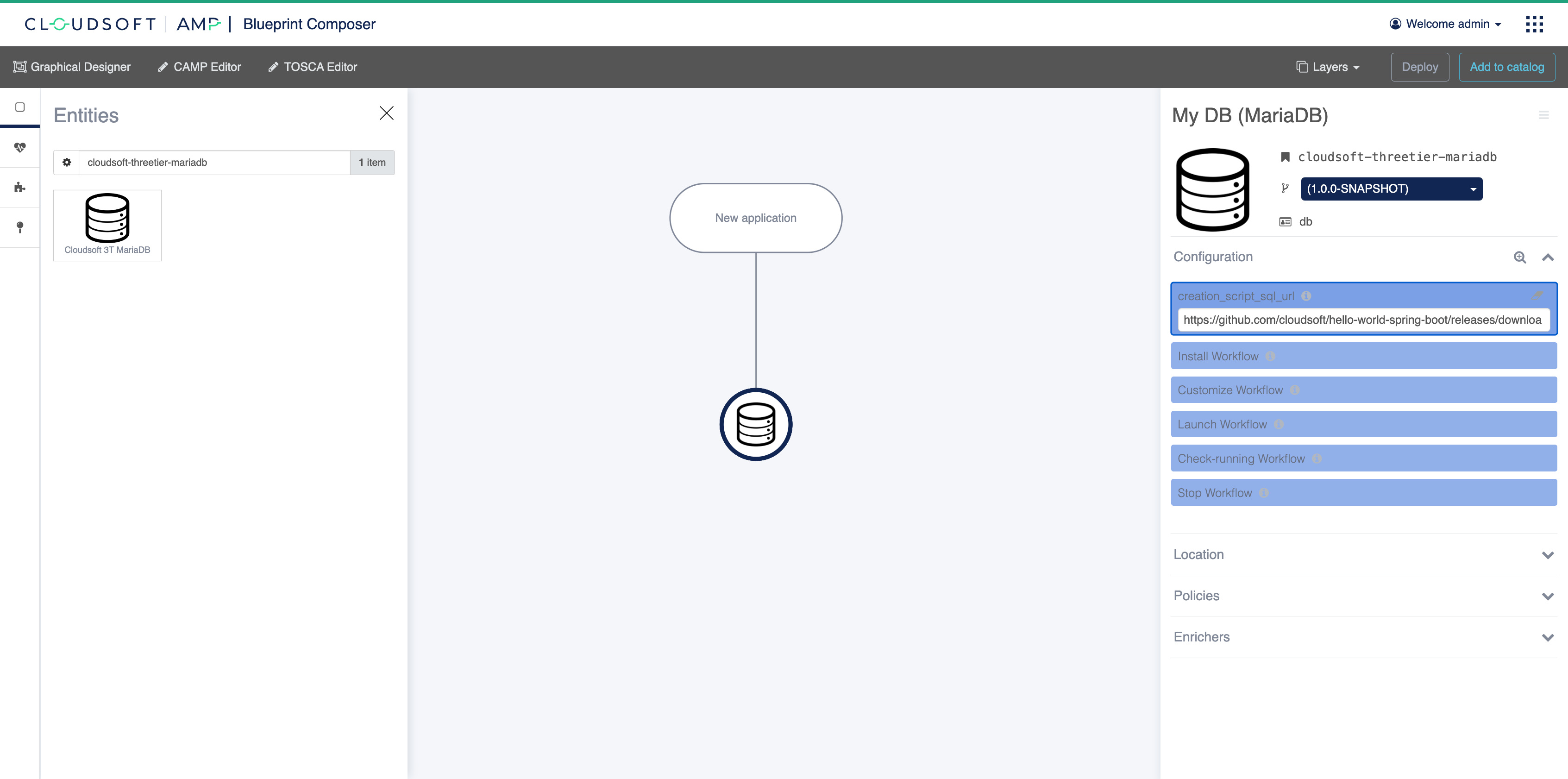
Set a name by entering My DB (MariaDB) instead of Cloudsoft 3T MariaDB.
Also give it a nice “reference ID”, a few lines below the title;
enter db instead of the random string next to the identity card.
This will simplify referring to sensor attributes of this entity when we come to inject the DB address
into the mid-tier.
Finally, set the configuration key creation_script_sql_url to the following value:
https://github.com/cloudsoft/hello-world-spring-boot/releases/download/1.0.1/creation-script-mariadb.sql
Your screen should now look like something similar to this:
Adding the web mid-tier: a cluster of Java Spring Boot nodes
For the mid-tier, we will use a “dynamic cluster” which allows resizing the number of nodes created from a “spec”.
Search the palette for the entity named DynamicCluster (org.apache.brooklyn.entity.group.DynamicCluster)
and drag & drop it onto the application node.
Once the entity is added into the graph, a new node will appear and the spec editor will then be displayed.
Set a name by entering My Cluster instead of Dynamic Cluster.
Do the same for the ID by entering cluster instead of the default value.
On the Configuration accordion, set the suggested Initial size (cluster.initial.size) configuration key to: 2.
all.
Set the Member spec (dynamiccluster.memberspec) configuration key by clicking on No spec set.
The palette will once again be displayed.
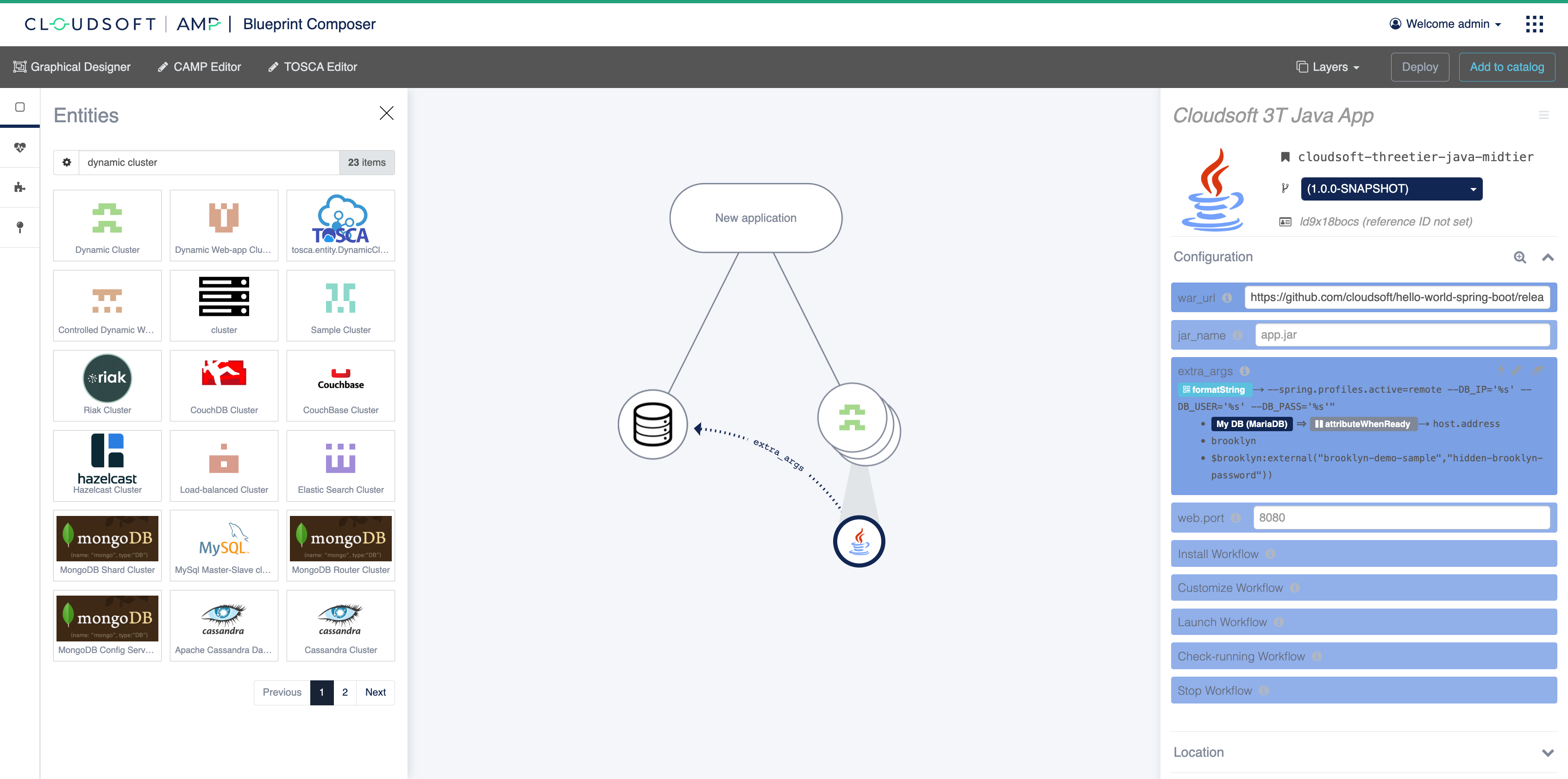
Select cloudsoft-threetier-java-midtier and enter the following configuration keys (Configuration accordion):
- For
war_url, use:https://github.com/cloudsoft/hello-world-spring-boot/releases/download/1.0.1/hello-world-spring-boot-1.0.1.jar -
For
extra_args, open the DSL editor by clicking on the lightning bolt icon. Select the kindFormatted stringand then set the following entries:--spring.profiles.active=remote --DB_IP='%s' --DB_USER='%s' --DB_PASS='%s'as the pattern$brooklyn:component("db").attributeWhenReady("host.address")to retrieve the address from ourdbnode, as the first argument (clickAdd argumentthen enter, or use theDSLeditor again to construct this)brooklynas the second argument (this is the user name expected in the creation script SQL)$brooklyn:external("brooklyn-demo-sample","hidden-brooklyn-password"))as the password; this references a built-in external secrets store (you can also configure other secrets store) which contains the password specified in the creation script SQL
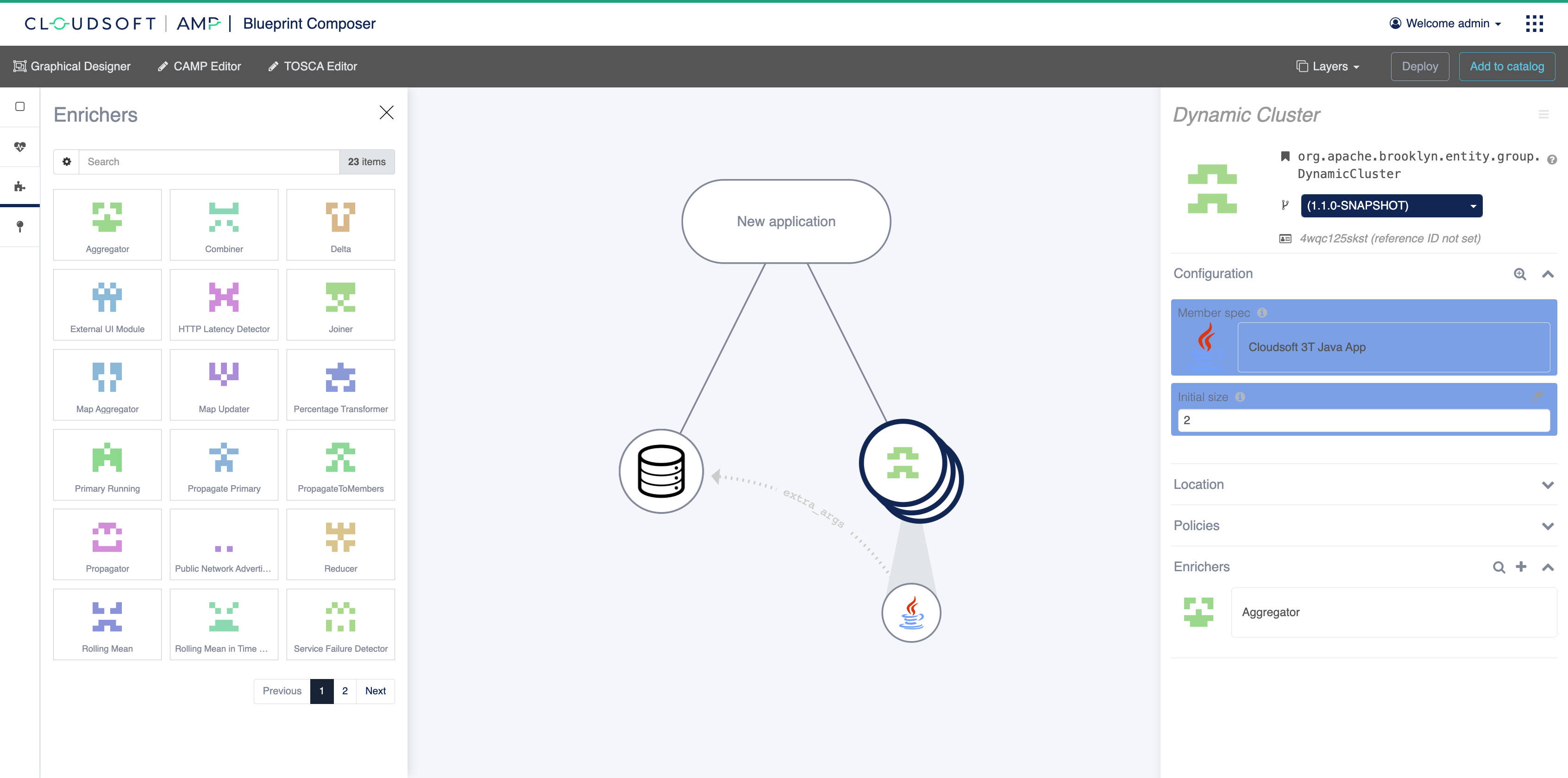
Then click Done to save. The spec editor should now display something similar to this:
We now need to collect the IP addresses of all nodes created in the dynamic cluster.
An “aggregator enricher” will do this.
Go back to the web cluster entity by clicking on the My Cluster cluster node on the graph.
Head over the Enrichers accordion and click on the “+” icon.
Similar to the cluster member spec in the previous step, search and select the Aggregator enricher and,
clearing any filters if necessary, add the following configuration keys (Configuration accordion):
enricher.sourceSensor=>$brooklyn:sensor("host.address")enricher.targetSensor=>$brooklyn:sensor("children_ips")enricher.aggregating.fromMembers=>trueenricher.transformation.untyped=>list
The canvas and the spec viewer should now display something similar to this:
Adding the load-balancer tier (Nginx)
Add a node for the web cluster by searching the palette for the entity named
Cloudsoft 3T Nginx (cloudsoft-threetier-nginx) and drag & drop it onto the application node.
Once the entity is added into the graph, a new node will appear and the spec editor will then be displayed once again. Set a name by entering My Load Balancer (nginx). Do the same for the ID by entering nginx instead of the default value.
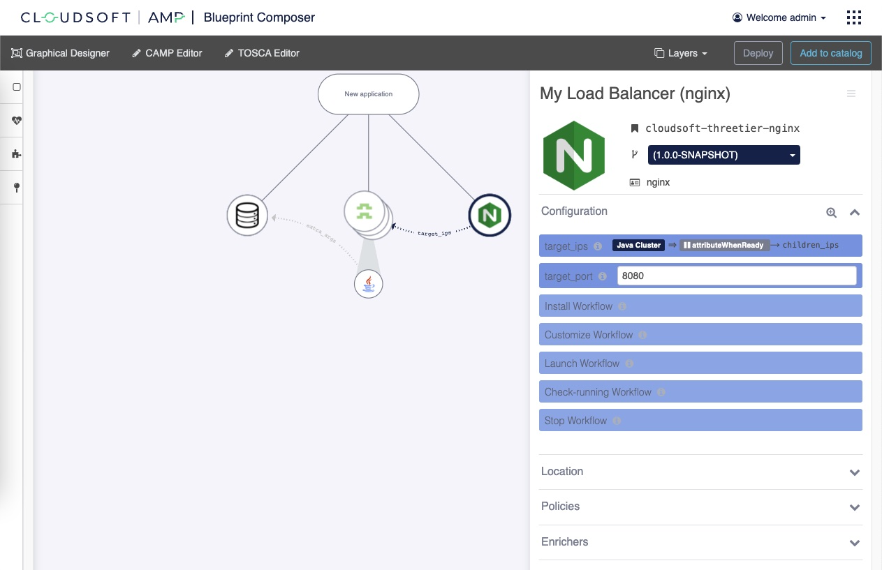
On the Configuration accordion, we need to set two values:
target_ips:$brooklyn:component("cluster").attributeWhenReady("children_ips")(set this as the value, not an entry, by clicking the</>code mode next to “No entries”; this is a DSL expression pointing to the list of IPs maintained by the aggregator enricher we just added at the cluster)target_port:8080(this is where the Spring Boot app runs)
The canvas and the spec viewer should now display something similar to this:
Setting the application title, location and propagate valuable sensor
Click on the application node (where it currently says New application) to bring up the spec editor.
Set a name by entering Cloudsoft 3T Three Tier Application instead of Unnamed Application.
Open the Location accordion and click on the Attach link.
This will display the palette with all available locations you can deploy your blueprint to.
Select the one you wish to use.
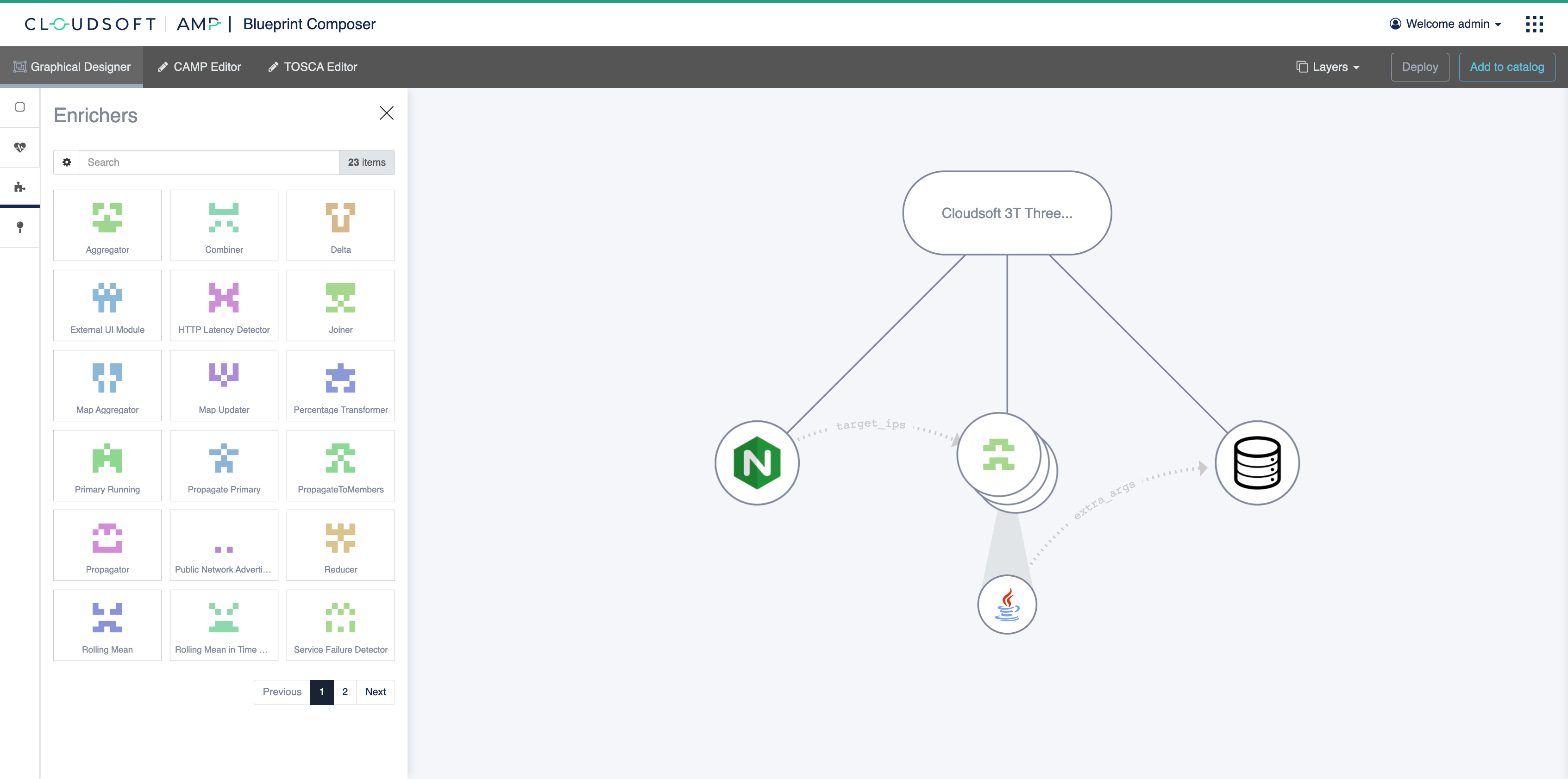
Finally rearrange the children nodes so they go logically from left-to-right as nginx, mid-tier, db.
The canvas and the spec viewer should display something similar to this:
Deploying
Finally, click “Deploy” to deploy the application. This will take a few minutes, but while deploying you can explore the inspector, showing the topology, the activities at each node, and as information becomes available, the sensors at each node.
When it is complete, the root application node Summary tab will show the web link at the top:
open this to see the deployed sample application.
If you encountered any issues, you can use the inspector to track the behavior. You could also try downloading the blueprint source code and pasting it into the “CAMP Editor”, or of course contact Cloudsoft.
The next tutorial will walk through the individual components.
Summary
The blueprint composer allows you to create and quickly compose applications with graphical visualisation of their status.
Next
- Explore more Tutorials